If you look closely at the photogate, you will notice that the top of one of the prongs has a symbol on it that looks like this:


Now we need to figure out how to connect the photogate to the Arduino, since the Arduino is what will provide power, ground the circuit, and run the program. We can figure out which pins are which by consulting the photogate's datasheet:
 |
| Image Source: https://www.sparkfun.com/datasheets/Components/GP1A57HRJ00F.pdf |
If you are new to electronics, this diagram may be confusing. It shows the internal components of the photogate, which we don't need to worry about. The important parts for us are the numbered pins. The diagram below is my translation of the datasheet, which I hope is a little clearer:

Both diagrams are drawn from the perspective of someone looking down at the photogate from above- the same perspective as the photo above. The diagrams show that we need to connect the bottom left pin and the top right pin to ground. Use jumper wires to connect these two pins to the ground bus, and another wire to connect the ground bus to one of the ground pins of the Arduino. We will use the blue bus on the breadboard for ground and the red bus for power.


The diagrams also show that the bottom right pin needs to be connected to a 220Ω resistor, and the other end of that resistor needs to connect to 5V. As a reminder, we connect two components by putting their leads in the same row. As you see in the photo below, one end of the resistor is in the same row as the bottom right pin of the photogate, and the other end is in row 8, which is connected to the power bus with a red wire:


We also need to connect the top left pin to the power bus, and the power bus to the 5V pin on the Arduino:


The last pin to connect is the middle left pin, the signal pin. This is the pin that the Arduino looks at when it needs to figure out whether the beam has been interrupted. For this circuit, you can choose any of the numbered digital and analog input/output pins. I chose to use digital pin 2. I used yellow wires for signal, but there isn't really a color convention for signal wires, so you can use any color you like (other than red and black, which are conventionally reserved for power and ground).


That's all you need to run a photogate! Now we'll add the LED to the circuit. An LED's circuit is pretty simple:
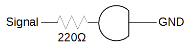
We'll use digital pin 9 as the signal pin for the LED.


Since we can place the LED anywhere in the circuit, I've put the negative lead directly into the ground bus. This has the same effect as putting the negative lead in a horizontal row and using a wire to connect that row to ground.
Now that the circuit is built, it's time to start writing the program, or sketch, that will tell it what to do. If you haven't installed and set up Arduino on your computer yet, you will need to do that in order to write and use Arduino programs. You can find instructions for that here.
Once you have opened a blank sketch, start with the skeleton of every Arduino program. Every program needs to contain the following lines:
void setup() {
// All code between these curly brackets will be executed once, when the program first starts up.
}
void loop() {
//Code in this section is executed over and over, several times per second.
}
Putting // at the beginning of a line makes that line a comment- the computer won't try to run anything that is written after the //. Comments are useful for keeping a record of what certain parts of the sketch are for, especially if other people may eventually be using your code.In the code below, I have used comments to describe what each line does, so that you can get a feel for how to write this kind of program.
//This sketch runs a SHARP GP1A57HRJ00F photo interrupter. When the photogate's
// signal is interrupted, the LED turns on. The signal pin of the photogate
// is wired to digital pin 2, and a 220 ohm resistor is between the anode
// and power. Runs on 5V. This sketch is good for testing whether a photo
// interrupter works.
int gateState = 1; //Creates an integer variable named gateState, and sets its value to be 1.
void setup() {
pinMode(2, INPUT); //Tells the Arduino that digital pin 2 is going to give it information.
pinMode(9, OUTPUT); //Tells the Arduino that it is going to give commands to digital pin 9.
}
void loop() {
gateState = digitalRead(2); //Each time the loop runs, set the value of gateState to be whatever
// value is coming in from pin 2.
if (gateState > 0) { //If the value of gateState is greater than zero,
digitalWrite(9, HIGH); //turn on the LED by sending high voltage (4.9V) to pin 9.
}
else { //Otherwise (that is, if the value of gateState is less than or equal to zero),
digitalWrite(9, LOW); //turn off the LED by sending low voltage (0V) to pin 9.
}
}
That's all there is to it! Once you have written the sketch, connect your Arduino to your computer with the USB cable and run it. When it is done uploading, you can test whether it's working by interrupting the photogate's beam (I used a pencil) and observing whether the LED turns on and off as it should.
Next week's tutorial will go over the complete circuit and code for the photogate setup we're using with the feeder, and it's considerably more complex. If you want to learn how to use photogates to do more useful and complicated things, I recommend reading up and doing some tutorials on the Arduino and/or Adafruit websites. Specifically,
are all relevant to next week's project. The Arduino Reference Page is also very helpful.
No comments:
Post a Comment