When I made my first flower model in SolidWorks, I had it tilted slightly upward to look more like a natural flower. However, since a key reason for using the flower is to provide a shaded area through which the photogate's bean can pass, we decided to make the flower parallel to the plate so that the sun won't shine into any of the flowers in the middle of the day. The body of the flower, therefore, ended up looking like this:
To begin the SolidWorks model, I sketched the contour of the flower (two lines connected by an arc) on the right plane and the flower opening (a circle 10 mm in diameter, exactly the distance between the two arms of the photogate) on an orthogonal (the front) plane. I created a swept surface by extruding the circle along the path on the right plane, and I added 2 mm of thickening to the surface to create a 3D feature. I added a 2 mm vertical line to the path describing the flower body in order for the bottom opening of the flower to lie flat.
The next task was to add petals to the flower. I created another sketch on the right plane to define the curvature and thickness of the petals (shown in blue below). Both the petals and the walls of the flower are 2 mm thick, resulting in a sturdy plastic object.
I revolved this sketch about the central axis of the flower to create the 3D feature. I then sketched the shape of the petals on the top plane (using the mirror feature to make the first petal symmetric and the circular pattern feature to repeat the petal eight times around the flower opening) and used that sketch as a sort of cookie cutter to cut the 3D feature into petal shapes:
I then cut an extrusion 0.5 mm deep into each petal to create nectar guides.
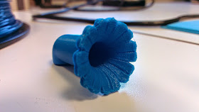
At this point, I printed the prototype. I exported an STL file of my model and took it to the MakerBot 3D printer in the engineering department. In order for the layers of plastic to be laid down correctly, the MakerBot software positions the model, if possible, so that each layer creates no more than a 45° overhang. I could print this prototype without needing to add any additional support structures. This was my first time using a 3D printer, so I was really excited to watch it as it printed the flower.
 |
| The entire flower is about 55 mm long. |
After playing with the position of the prototype on the feeder, we determined that it was too long (the entrance to the flower stuck out farther than the edge of the wooden platform), so I shortened the straight portion of the flower by one-third. Furthermore, since the length of a drinking slot on the feeder is 10 mm but half of it is underneath the jar (see the photo of the feeder in this post), I added a cylinder the size of the jar to my model and used it to cut the back off of the flower, so the flower can sit snugly against the jar:
Then, following the principle of adding a part of the feeder that interfaces with the flower to the model in order to cut into the flower, I modified the flower to hold a photogate. I positioned the photogate near the back of the flower so that the infrared beam will be interrupted continuously while a bee is drinking, and low enough so that the beam is 4.5 mm from the floor of the flower and will therefore likely intersect the bee's body. I first created a sketch of the shape of the photogate on a plane intersecting the flower, adding to the width of the photogate arms where I wanted the flower wall to be cut, and extruded that cut to create an opening for the photogate beam:
After that, I built a piece to hold the photogate snugly in place by sketching and extruding a platform for the photogate to sit on top of:
I also added arms to secure the photogate, keeping it from sliding forward or backward.


No comments:
Post a Comment