My project in the Bee Lab is to design a “smart hive” for honey bees: a way to automatically keep track of how successful they are at gathering nectar from flowers. The data we are interested in is the weight of the hive, which tells us how much nectar they’ve collected, and the number of bees that enter and exit the hive, which tells us how much effort they’ve put into collecting nectar. We plan to measure activity by using sensors mounted at the front of the hive which the bees must walk past to enter or exit, to measure weight with an electronic scale, and to log the data onto a Micro SD Card using an Arduino Mega.
Since my last post regarding the smart hive project, a lot has happened.
We’ve successfully connected the electronic scale to the Arduino, tried out an existing Instructable on how to make a honey bee counter, scrapped that after some difficulties, and gone back to our original plan of using photo-interrupter gates (modeled after an earlier project to build an automated feeder to count bees). In the process, we’ve switched from using a Teensy 2.0++ to an Arduino 2650 Mega, determined how we will power the system, and how we will house and protect the electronics from weather. We’ve also changed the style of bee corral, which is the device mounted at the hive entrance that houses the sensors, and the kind of sensors we are using. While some of it took some time and figuring out, overall we’ve made some reasonable progress.
 |
| Old Hive setup . [1] |
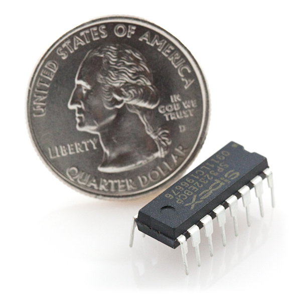
The serial communication between the scale and the Mega is finally working thanks to a MAX3232 chip and circuit, which converts voltages between the scale and the Mega. We can control specific aspects of the scale via the Arduino. However, occasionally there’s a problem where incorrect characters are communicated. To fix this, we will need to implement some sort of safety mechanism. The serial communication voltage converter board has been soldered onto a circuit board. When the circuit was on a breadboard the communication was significantly less reliable, perhaps due to a poor connection. Upon connecting the circuit more reliably there have been significantly fewer bad strings returned to the serial port. When the serial communication outputs something correctly there are a couple of things that are consistent, even when the weight is changing. We know that the zeroth, first, third and fourth characters returned must be a value from 0 to 9, the second character must be a “.”, and the last two characters must be “kg”. Since the scale’s print and on and off functions can be controlled by the Arduino, we can implement a safety mechanism whereby the data is only logged to the SD card if the above constraints are met, which would greatly reduce if not completely eliminate the problem regarding incoherent strings returned via the serial port. If it takes multiple attempts it shouldn’t be an issue since we are not continuously logging the scale data but rather will measure the hive weight on some interval such as once per hour.
 |
| MAX3232 Chip. [2] |
When we decided to change the type of sensors, we had to redesign the bee corrals to accommodate the photo-interrupters and channel bees effectively into their path.
 |
| Photo-interrupter gate. [3] |
Using SolidWorks, we’ve designed and 3D-printed a new plastic barrier that goes over the front of the hive, and houses 12 photo-interrupters in 6 bee-sized passageways. The barriers were designed to such that there are two per hive entrance.
 |
| Bee Corral. [4] |
There are two photo-interrupters per passage so we can separately track entries and exits. Now, the newly printed bee corrals need the photo-interrupters installed. We also need to print and design a new circuit to accommodate the photo-interrupters.
One of our concerns regarding the bee counter was the number of pins it uses. Since there are two photo-interrupters per passageway they use a lot of pins. Furthermore the scale requires six pins, two of which must be pins 2 and 3. The SD data logger requires six pins. Initially we were concerned that we wouldn’t be able to use the SD data logger and the scale because the SD logger appeared to need pins 2 and 3; however, it turns out that while it mounts into pins 2 and 3 for support, they aren’t required. Phew! Unfortunately the Teensy 2.0++ couldn’t accommodate our needs, which is why we switched to using an Arduino 2650 Mega. Since the Mega is better equipped than the Teensy 2.0++, such that is has more pins and serial ports, we plan to continue using the Mega even with the new design.
Despite the considerable setbacks that took place in trying to use the Teensy 2.0++, different sensors and a different circuit board, overall the project is moving along pretty well. The next steps are to write the code for data logging, scale control, and bee counting. In addition, we need to better connect the MAX3232 circuit, design a circuit for the new sensors and create a nice enclosure for the electronics that is safe from the weather.
Media Credits:
[1] Photograph from demonstration (Image copyright of Harvey Mudd College)
[1] Photograph from demonstration (Image copyright of Harvey Mudd College)
[4] From Solidworks Design
No comments:
Post a Comment